Multiple UPSs on RS-485: Confirm the Bus, Not Just the Connector
By Highidea Power · 24 October 2026 · 4 min read
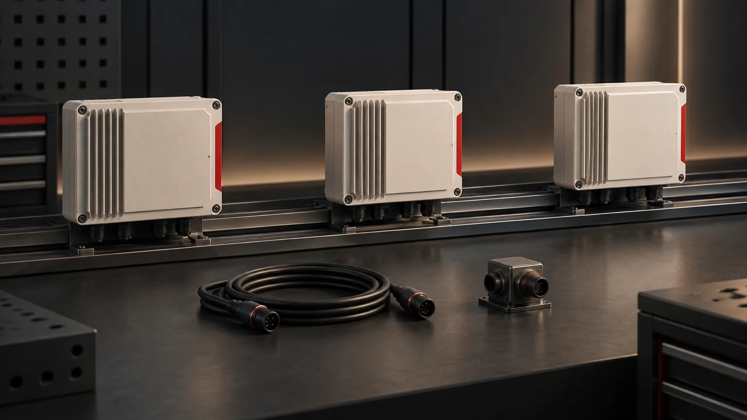
Confirm the electrical bus, supported protocol, addressing and receiving-system behaviour before placing several UPS interfaces on one RS-485 network. The RS-485 designation describes an electrical interface; it does not define the complete protocol, connector pinout or application map. A multi-device integration needs a documented common arrangement.
Turn the proposed network into a requirement
A facilities team may want one BMS to collect several UPSs rather than install independent monitoring routes. Begin with the required points, update expectations and the service consequence of lost visibility. Then list each UPS, interface option and receiving device.
Highidea offers communication options on compatible equipment. Ask for the applicable host/card combination and protocol information for your intended receiving system. Our interface-selection guide helps choose the broad route; this article develops the extra questions once a shared serial bus is proposed.
Separate three compatibility layers
First, the electrical layer includes the actual transceiver, loading, cable arrangement and relevant reference or isolation requirements. Second, the protocol layer includes the supported message format, mode, rates and device addressing. Third, the application layer defines which values or states are available and how the receiver interprets them.
Texas Instruments' AN-1057 explains that RS-485 specifies electrical characteristics rather than a connector, cable or protocol. Its discussion also distinguishes unit loads from a simple device count. Do not convert a familiar historical node number into a universal capacity statement for every modern interface.
A matching connector shell closes none of these layers by itself. Keep pinout, supported functions and the receiving platform's limits in the actual product documentation. A supplier should identify the complete compatibility basis, not merely repeat the letters RS-485.
Prepare a bus-eligibility schedule
Use the same schedule for the UPS supplier and the BMS integrator. A missing answer should have an owner before equipment is ordered or connected.
Layer | Information to confirm |
|---|---|
Devices | Exact UPS/interface identities, revisions and approved multi-device support. |
Electrical network | Cable arrangement, loading, applicable distance/rate conditions and isolation/reference requirements. |
Protocol | Supported protocol and mode, communication parameters, addressing and message ownership. |
Receiver | Device capacity, polling arrangement, timeout handling and supported application map. |
Verification | Representative final combination, expected values, missing-device indication and restoration evidence. |
Termination, bias and shielding belong to the complete qualified design and product instructions. This schedule supplies no resistor value, pin connection or universal cable length. A live network should not be rewired to discover whether the proposed arrangement works.
Work a mixed-device example
Suppose two hypothetical UPS interfaces both list RS-485, but their protocol documents use different application maps or incompatible operating modes. The electrical label does not make the receiver understand both. The design may need another supported interface or an explicitly compatible gateway arrangement.
In another hypothetical network, all devices support the required protocol, but two share an address. A communication problem in that arrangement is different from a scaling error after a valid response. Preserve identity and the approved parameter record so troubleshooting can separate the layers.
Our data-dictionary guide helps define the meaning of each point after transport compatibility is established. Do not assume a protocol name supplies every required battery, runtime or alarm field.
Include missing-device behaviour
A shared bus can leave the receiving system with old values when a device stops responding. Agree how that state appears, how the source identity is preserved and what restoration evidence is needed. A retained numeric value should not silently look like a fresh measurement.
The network's electrical and protocol design should also address message ownership and relevant contention conditions. Do not assume several independent pollers can share a network because each works alone. The responsible integrator should document the supported arrangement and its limits.
Use an authorized representative environment for commissioning. Record exactly which devices, versions, cable arrangement and receiver configuration were verified. A single-device bench result is useful evidence, but it is not a test of the final multi-device network. Keep the remaining difference visible until accepted.
Send the complete monitoring enquiry
Through our contact page, share the proposed device list, receiving platform, required points, installation constraints and monitoring outcome. Highidea can discuss the compatible equipment options and applicable protocol information with your integration team.
Reference
Texas Instruments: AN-1057 Ten Ways to Bulletproof RS-485 Interfaces, revised 2013.
FAQ
Frequently asked questions
Does RS-485 always mean Modbus?
No. Confirm the actual supported protocol and mode from the device documentation and the receiver's requirements.
Can every node use the same address?
Use the protocol and implementation's approved addressing arrangement. Device identity must remain unambiguous to the intended receiver.
Does electrical communication prove correct alarm interpretation?
It establishes only part of the path. Point meanings, state mapping, freshness and event handling need their own verification.
Related
Products, solutions & further reading.
Put this into practice
Need help specifying the right unit?
Share the load, voltage, runtime, environment and destination for a configuration review.