Generator, Rectifier, Battery and Inverter: Mapping the Telecom Backup Chain
By Highidea Power Engineering Team · 24 September 2026 · 5 min read
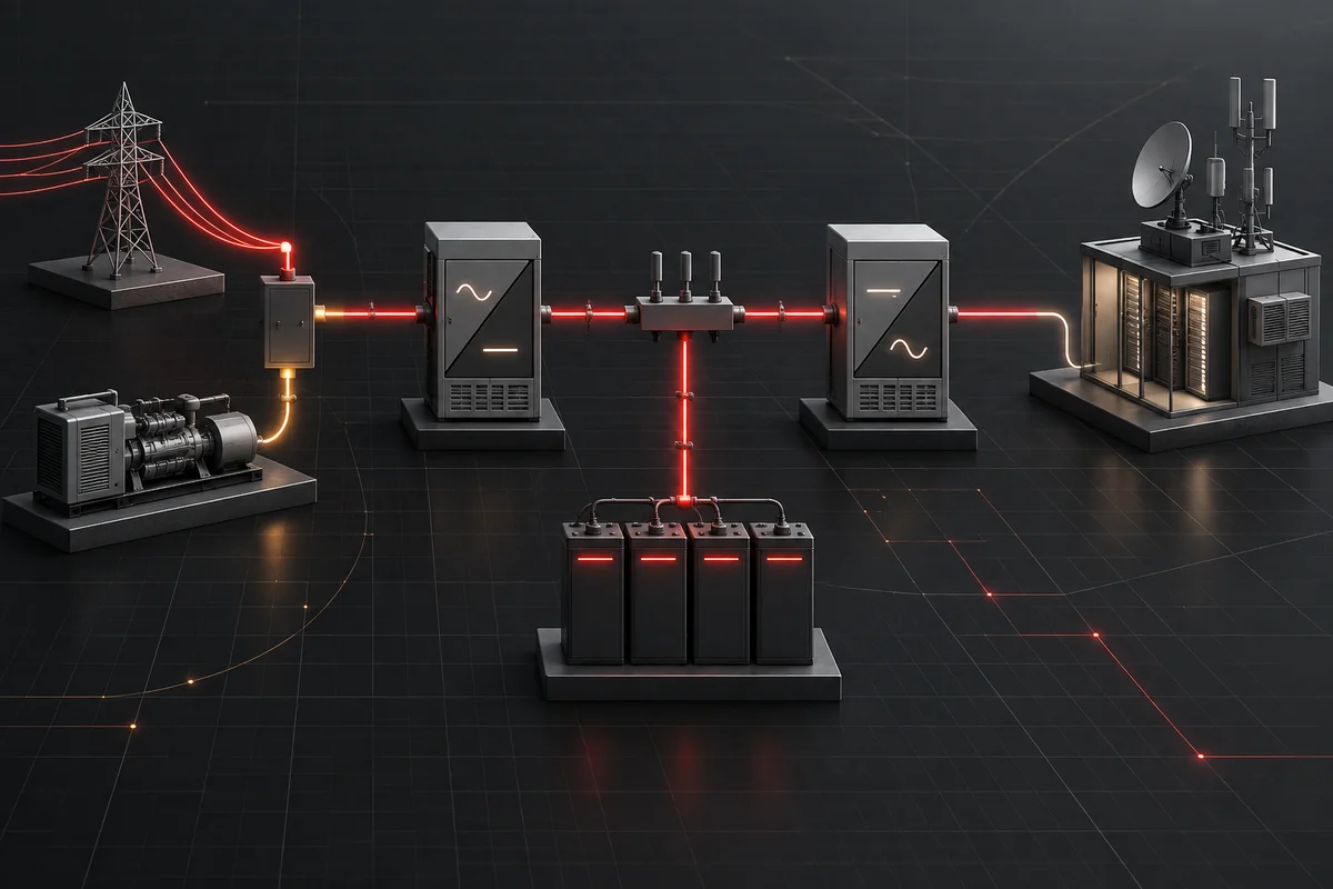
A telecom backup chain should be mapped from every energy source to each critical load. Utility or generator AC commonly feeds a rectifier and DC bus; batteries support that DC bus; an inverter supplies AC loads from DC; protection, bypass, controls and monitoring determine how the chain behaves during loss and restoration. The exact priorities and paths remain site-specific.
The decision in practical terms
Telecom power designs often combine an AC source, a DC plant, energy storage and protected AC loads. A DC-to-AC inverter is one element in that chain, so its input window, source priority, transfer behavior, output quality and monitoring interfaces must match the site architecture. The practical question here is: “How do the major components of a telecom site power chain interact?” The result is a decision record that engineering, procurement and the supplier can all verify.
For “How do the major components of a telecom site power chain interact?” Before discussing a model, close the source and load facts, define acceptable operation, and decide what evidence will count as acceptance. The first three items to close are: Draw utility, generator, rectifier, DC distribution, battery, inverter, AC distribution and critical loads on one source-to-load diagram with normal and backup paths marked. Record the operating voltage range, current, protection, grounding and capacity at each interface, including generator pickup, battery discharge and recharge conditions. Define and witness the event sequence for AC loss, generator start, rectifier recovery, battery support, inverter alarms and return to normal operation. Once these are controlled, differences between proposals become visible and testable.
Five checks that change the recommendation
Draw utility, generator, rectifier, DC distribution, battery, inverter, AC distribution and critical loads on one source-to-load diagram with normal and backup paths marked. Link the requirement to the exact drawing, measurement, report or supplier declaration used to close it. Keep revisions visible when the configuration changes.
Record the operating voltage range, current, protection, grounding and capacity at each interface, including generator pickup, battery discharge and recharge conditions. Describe the acceptable result before testing or document review begins. Evidence is easier to judge when pass, deviation and rework outcomes are already defined.
Define and witness the event sequence for AC loss, generator start, rectifier recovery, battery support, inverter alarms and return to normal operation. Check the boundary of the answer: model, option, load, environment, market and date. A correct statement can become misleading when any of those changes.
Specify remote alarms, control, protocol, cybersecurity ownership and integration with the site monitoring system. Preserve the decision in the purchase file so engineering, procurement, commissioning and service teams work from the same approved condition.
Inventory AC loads in watts and VA, including startup demand and tolerance to transfer events. Put the value and its source in the technical schedule. A supplier should be able to point to the exact model, operating mode and condition used for the recommendation.
Make supplier proposals comparable
Require line-by-line responses to a single project brief. A compliant offer should expose assumptions and exceptions instead of burying them in general literature. For “Generator, Rectifier, Battery and Inverter: Mapping the Telecom Backup Chain,” reject any response that silently changes a material project condition or evidence scope.
Keep materially different configurations as separate alternatives; combining them in one price table can conceal technical risk.
Review item | Requirement to state | Decision record |
|---|---|---|
Technical check 1 | Draw utility, generator, rectifier, DC distribution, battery, inverter, AC distribution and critical loads on one source-to-load diagram with normal and backup paths marked. | Record the evidence, responsible approver and effect on the guide decision. |
Technical check 2 | Record the operating voltage range, current, protection, grounding and capacity at each interface, including generator pickup, battery discharge and recharge conditions. | Record the evidence, responsible approver and effect on the guide decision. |
Technical check 3 | Define and witness the event sequence for AC loss, generator start, rectifier recovery, battery support, inverter alarms and return to normal operation. | Record the evidence, responsible approver and effect on the guide decision. |
Technical check 4 | Specify remote alarms, control, protocol, cybersecurity ownership and integration with the site monitoring system. | Record the evidence, responsible approver and effect on the guide decision. |
Verify the approved requirement
Turn the agreed requirement into a verification record. Identify the exact supplied item and configuration, the evidence or test method, the applicable condition and the expected result for the question “How do the major components of a telecom site power chain interact?” For performance tests, retain instruments, readings, alarms and timestamps; for document reviews, retain the issuer, scope and revision.
Retain the test data or document review with the serialised or otherwise identifiable delivered configuration. A successful verification applies only to the delivered configuration and stated conditions; it is not a blanket guarantee for a different load, site, document scope or operating mode.
Common failure modes in this decision
These common approaches can make an apparently complete specification impossible to approve with confidence.
- Ordering from the label “−48 V” without the operating range
- Ignoring DC-side current and cable loss
- Assuming every interface is standard on every model
- Answering “How do the major components of a telecom site power chain interact?” without naming the exact configuration and evidence
Where Highidea fits
Highidea documents dedicated power and telecom inverter families, including isolated DC-to-AC applications. Exact DC input, AC output, transfer path and parallel capability remain model-specific.
Share the completed schedule with Highidea and request a configuration-specific response covering the host, energy storage, interfaces, options and evidence.
Copy this into your RFQ
The list below is ready for an RFQ once project-specific limits and commercial terms have been added.
- Confirm in the quotation: Draw utility, generator, rectifier, DC distribution, battery, inverter, AC distribution and critical loads on one source-to-load diagram with normal and backup paths marked.
- Confirm in the quotation: Record the operating voltage range, current, protection, grounding and capacity at each interface, including generator pickup, battery discharge and recharge conditions.
- Confirm in the quotation: Define and witness the event sequence for AC loss, generator start, rectifier recovery, battery support, inverter alarms and return to normal operation.
- Confirm in the quotation: Specify remote alarms, control, protocol, cybersecurity ownership and integration with the site monitoring system.
- Confirm in the quotation: Inventory AC loads in watts and VA, including startup demand and tolerance to transfer events.
Authoritative references and scope
The cited material is authoritative background, not automatic proof of conformity or performance for a particular product.
ITU: ITU-T L.1210 — Sustainable power-feeding solutions for IMT-2020 networks
ITU: ITU-T K.152 — EMC requirements for telecom-facility power equipment
FAQ
Frequently asked questions
How do the major components of a telecom site power chain interact?
A telecom backup chain should be mapped from every energy source to each critical load. Utility or generator AC commonly feeds a rectifier and DC bus; batteries support that DC bus; an inverter supplies AC loads from DC; protection, bypass, controls and monitoring determine how the chain behaves during loss and restoration. The exact priorities and paths remain site-specific.
How can buyers make supplier answers easier to compare?
Send the exact load and source data, required operating outcome, site conditions, interfaces, target market and evidence requirements. For this decision, include: Draw utility, generator, rectifier, DC distribution, battery, inverter, AC distribution and critical loads on one source-to-load diagram with normal and backup paths marked. Record the operating voltage range, current, protection, grounding and capacity at each interface, including generator pickup, battery discharge and recharge conditions. Define and witness the event sequence for AC loss, generator start, rectifier recovery, battery support, inverter alarms and return to normal operation.
Can one datasheet establish the complete project scope?
Use family information to shortlist an architecture, but confirm the exact model, configuration, operating mode, test conditions and document scope in the quotation or approved technical schedule.
Related
Products, solutions & further reading.
Put this into practice
Need help specifying the right unit?
Share the load, voltage, runtime, environment and destination for a configuration review.