Telecom Power Acceptance Testing: From DC Bus to Critical AC Load
By Highidea Power Engineering Team · 5 October 2026 · 5 min read
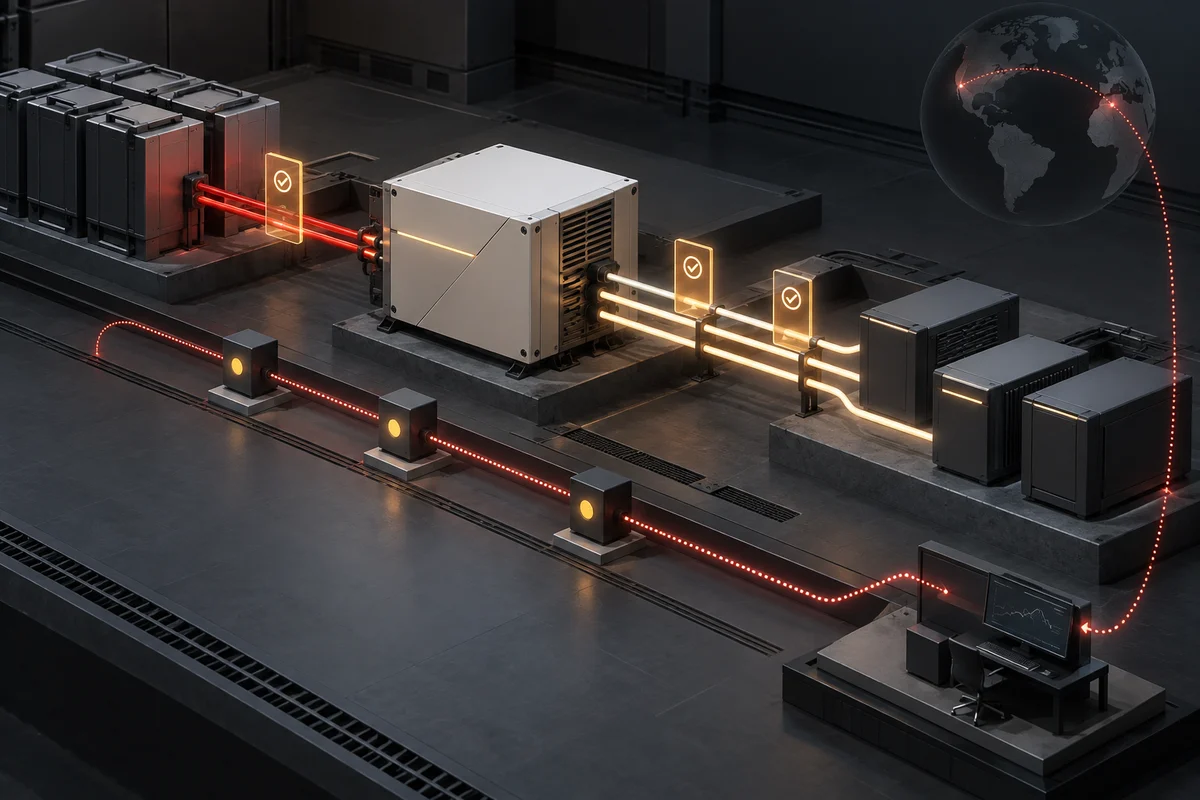
A telecom power acceptance test should witness the complete path from the live DC bus and alternate source through the inverter to representative critical AC loads. Record source limits, load condition, transfer events, output quality, alarms, monitoring delivery and recovery against approved criteria for the exact configuration; a successful functional test does not create a broader product or site conformity claim.
The decision in practical terms
Telecom power designs often combine an AC source, a DC plant, energy storage and protected AC loads. A DC-to-AC inverter is one element in that chain, so its input window, source priority, transfer behavior, output quality and monitoring interfaces must match the site architecture. The practical question here is: “What should a buyer witness when commissioning a telecom inverter?” Use the checks below to turn that question into a comparable supplier requirement.
For “What should a buyer witness when commissioning a telecom inverter?” Start with the operating facts, state the outcome the site needs, and require each supplier to map one exact configuration to both. The first three items to close are: Freeze the source-to-load diagram, DC operating range, grounding, protection, source priority, bypass path and representative AC load before the witness test begins. Run agreed normal, source-loss, abnormal-DC, overload-warning, bypass and restoration events while recording input, output, timestamps, alarms and load response. Prove that every required signal reaches the named monitoring system and responder, then close deviations, configuration records and rollback instructions before acceptance. Once these are controlled, differences between proposals become visible and testable.
Five checks that change the recommendation
Freeze the source-to-load diagram, DC operating range, grounding, protection, source priority, bypass path and representative AC load before the witness test begins. Put the value and its source in the technical schedule. A supplier should be able to point to the exact model, operating mode and condition used for the recommendation.
Run agreed normal, source-loss, abnormal-DC, overload-warning, bypass and restoration events while recording input, output, timestamps, alarms and load response. Treat this as an acceptance input, not a conversation note. If it changes after quotation, record the effect on capacity, battery, interfaces, evidence and delivery.
Prove that every required signal reaches the named monitoring system and responder, then close deviations, configuration records and rollback instructions before acceptance. Verify it with a measurement, drawing, nameplate, manufacturer requirement or approved project document. An unstated assumption here can invalidate the rest of the selection.
Confirm the real DC-bus nominal and operating range, polarity, grounding and protection scheme. Ask competing suppliers to answer this item with the same scope, condition and evidence format. That makes the proposals technically comparable before price is considered.
Define source priority and the expected behavior during AC loss, DC abnormality, bypass and restoration. Assign an owner to confirm this point before sample or commissioning tests. The final record should show both the required value and the evidence that the delivered system meets it.
Make supplier proposals comparable
Issue the same controlled requirement to every bidder and ask each response to show assumptions, deviations and optional items beside the relevant line. For “Telecom Power Acceptance Testing: From DC Bus to Critical AC Load,” reject any response that silently changes a material project condition or evidence scope.
Resolve technical differences before comparing price; two offers based on different loads, environments or evidence scopes are not equivalent.
Review item | Requirement to state | Decision record |
|---|---|---|
Technical check 1 | Freeze the source-to-load diagram, DC operating range, grounding, protection, source priority, bypass path and representative AC load before the witness test begins. | Record the evidence, responsible approver and effect on the guide decision. |
Technical check 2 | Run agreed normal, source-loss, abnormal-DC, overload-warning, bypass and restoration events while recording input, output, timestamps, alarms and load response. | Record the evidence, responsible approver and effect on the guide decision. |
Technical check 3 | Prove that every required signal reaches the named monitoring system and responder, then close deviations, configuration records and rollback instructions before acceptance. | Record the evidence, responsible approver and effect on the guide decision. |
Technical check 4 | Confirm the real DC-bus nominal and operating range, polarity, grounding and protection scheme. | Record the evidence, responsible approver and effect on the guide decision. |
Verify the approved requirement
Turn the agreed requirement into a verification record. Identify the exact supplied item and configuration, the evidence or test method, the applicable condition and the expected result for the question “What should a buyer witness when commissioning a telecom inverter?” For performance tests, retain instruments, readings, alarms and timestamps; for document reviews, retain the issuer, scope and revision.
Keep the verification with the approved configuration so later changes can be assessed against the same baseline. A successful verification applies only to the delivered configuration and stated conditions; it is not a blanket guarantee for a different load, site, document scope or operating mode.
Common failure modes in this decision
A shortcut that hides a boundary or cannot be verified should be clarified before approval.
- Ordering from the label “−48 V” without the operating range
- Ignoring DC-side current and cable loss
- Assuming every interface is standard on every model
- Answering “What should a buyer witness when commissioning a telecom inverter?” without naming the exact configuration and evidence
Where Highidea fits
Highidea documents dedicated power and telecom inverter families, including isolated DC-to-AC applications. Exact DC input, AC output, transfer path and parallel capability remain model-specific.
Send Highidea the confirmed inputs above so the quotation can identify the applicable host, battery arrangement, interfaces, options and supporting documents.
Copy this into your RFQ
Adapt these lines to the project and replace every unknown with an explicit supplier question.
- Confirm in the quotation: Freeze the source-to-load diagram, DC operating range, grounding, protection, source priority, bypass path and representative AC load before the witness test begins.
- Confirm in the quotation: Run agreed normal, source-loss, abnormal-DC, overload-warning, bypass and restoration events while recording input, output, timestamps, alarms and load response.
- Confirm in the quotation: Prove that every required signal reaches the named monitoring system and responder, then close deviations, configuration records and rollback instructions before acceptance.
- Confirm in the quotation: Confirm the real DC-bus nominal and operating range, polarity, grounding and protection scheme.
- Confirm in the quotation: Define source priority and the expected behavior during AC loss, DC abnormality, bypass and restoration.
Authoritative references and scope
These primary sources support the industry explanation and checklist; product compliance or performance still requires evidence for the quoted model and configuration.
ITU: ITU-T L.1210 (12/2025) — Sustainable power-feeding solutions for IMT-2020 networks
ITU: ITU-T K.152 — EMC requirements for power equipment in telecommunication facilities
FAQ
Frequently asked questions
What should a buyer witness when commissioning a telecom inverter?
A telecom power acceptance test should witness the complete path from the live DC bus and alternate source through the inverter to representative critical AC loads. Record source limits, load condition, transfer events, output quality, alarms, monitoring delivery and recovery against approved criteria for the exact configuration; a successful functional test does not create a broader product or site conformity claim.
What information should I send to the UPS supplier?
Send the exact load and source data, required operating outcome, site conditions, interfaces, target market and evidence requirements. For this decision, include: Freeze the source-to-load diagram, DC operating range, grounding, protection, source priority, bypass path and representative AC load before the witness test begins. Run agreed normal, source-loss, abnormal-DC, overload-warning, bypass and restoration events while recording input, output, timestamps, alarms and load response. Prove that every required signal reaches the named monitoring system and responder, then close deviations, configuration records and rollback instructions before acceptance.
Can a family-level brochure replace model-specific confirmation?
Use family information to shortlist an architecture, but confirm the exact model, configuration, operating mode, test conditions and document scope in the quotation or approved technical schedule.
Related
Products, solutions & further reading.
Put this into practice
Need help specifying the right unit?
Share the load, voltage, runtime, environment and destination for a configuration review.