Why Two Meters Can Disagree on UPS Output Voltage
By Highidea Power · 22 October 2026 · 3 min read
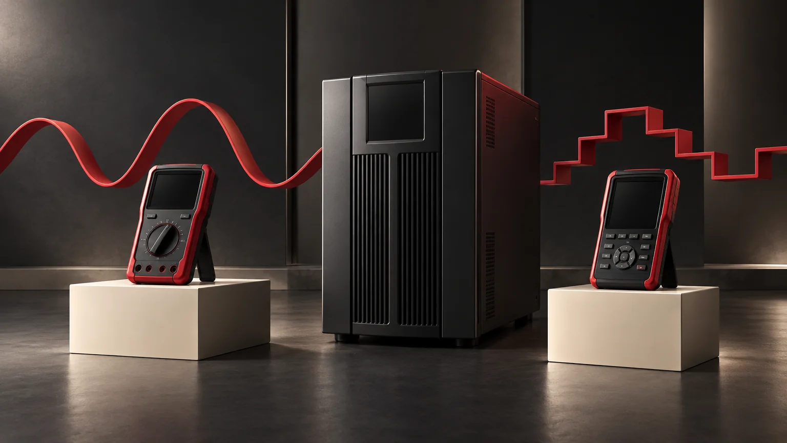
Two different readings are a reason to compare measurement conditions before adjusting a UPS. Establish the same point, operating mode, load and time period, then compare the meters' measurement methods and specifications. An average-responding meter and a true-RMS meter can report different values on a non-sinusoidal waveform. The label “true-RMS” still needs its stated range and waveform conditions.
Highidea offers online and line-interactive UPS routes with different output behavior. Understanding the measurement helps you compare the selected model with the load's requirements, without changing settings to chase an unexplained number.
First make the records comparable
Ask qualified measurement personnel to assemble the record below using approved safe access. This is a comparison worksheet, not a list of live probing points.
Record | What belongs beside each reading |
|---|---|
Electrical boundary | Named output or approved measurement location; distinguish the UPS output from a downstream extension or distribution point. |
Operating condition | Normal, battery or bypass state, relevant load and whether the observation covers steady operation or a transition. |
Instrument identity | Exact meter, selected function, range, current specification and calibration/service status. |
Method limits | Average responding or true-RMS; AC or AC+DC function as applicable; bandwidth, crest-factor and other specified limitations. |
Time and evidence | Original value, unit, time basis, observation interval and any independent waveform record obtained safely. |
Readings taken at different locations or during different events may both describe their own conditions correctly. Resolve this before deciding that the meters disagree about the same voltage.
Why the method matters
RMS means root mean square. It expresses an effective value related to heating in a resistance. An average-responding instrument uses a conversion that is appropriate for the waveform specified by its manufacturer, commonly a sine wave. A distorted or stepped waveform can make that conversion unsuitable.
Fluke's explanation distinguishes average-responding and true-RMS instruments and discusses non-sinusoidal measurements. Its illustrative error figures are not a universal correction factor. Do not multiply an unexplained reading by a percentage from an educational example to obtain a supposedly correct UPS voltage.
A true-RMS instrument also has limits. Its manual should define applicable frequency, amplitude, crest factor and function. A suitable method used outside its specifications may still give an unreliable comparison.
A hypothetical disagreement
Suppose one instrument is average responding and the other true-RMS. They observe a non-sinusoidal battery output under comparable steady conditions. Different displayed values can be consistent with their different methods.
That finding does not prove which value meets the equipment specification. The measurement must also match the specification's quantity and conditions. A UPS display may use its own sampling and update process, so it should be another identified observation, not an automatic referee.
If the instruments are both suitable and their records are comparable, retain the discrepancy for investigation. A supply-path difference, transient or instrument problem remains possible. Avoid choosing the value closest to the nominal voltage merely because it looks reassuring.
Close the discrepancy in order
- Preserve both original records and the reported equipment symptom.
- Resolve differences in location, operating state, timing and measured quantity.
- Check the instruments against their own specifications and the required method.
- Have qualified personnel select any further safe, representative measurement.
- Compare the supported result with the load's permitted supply conditions and the exact UPS specification.
Keep enclosures closed unless an authorized service procedure requires otherwise. Never improvise an oscilloscope connection or protective-earth arrangement to investigate a reading.
Choose the output behavior your load needs
Our waveform selection guide explains the load question; ET1-3KR provides a rack online product route. For a reading discrepancy, send Highidea the meter identities, conditions, original readings and load requirements so the discussion starts from comparable information.
Measurement reference
- Fluke: What is true-RMS?. Consult the actual meter manual for its limits.
FAQ
Frequently asked questions
Is nominal voltage the value every meter must display?
Nominal voltage is a reference. The applicable output tolerance and measurement conditions come from the selected model and project requirements.
Can a stable reading establish acceptable transfer behavior?
A steady display cannot establish the duration or shape of a short transition. That is a separate measurement task with its own suitable instruments and safe plan.
Can an old reading be compared with a new meter reading?
Only with its time and condition preserved. Confirm that both represent the same electrical boundary and operating state before interpreting the difference. A stored value, different averaging interval or changed load may explain a mismatch without establishing either instrument is defective. Keep the original readings and units.
Related
Products, solutions & further reading.
Put this into practice
Need help specifying the right unit?
Share the load, voltage, runtime, environment and destination for a configuration review.