Vehicle-Mounted UPS Input Sources: Shore Power, Generator and Onboard Conversion
By Highidea Power Engineering Team · 13 October 2026 · 4 min read
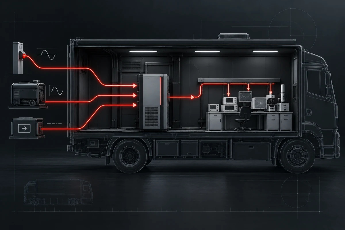
A vehicle-mounted UPS should not be selected from one nominal input voltage. Document every upstream source—shore connection, generator and onboard inverter or converter—plus its voltage, frequency, grounding, distortion, interruption and operating sequence. Then verify which source may feed the UPS, how sources are interlocked, what the protected instrument tolerates and what happens during transfer, engine start, cable disconnection and restoration.
Draw the mobile power states first
A mobile laboratory or command vehicle can be parked on shore power, running from a generator, moving on vehicle-derived power or temporarily operating from stored energy. Each state can present a different voltage window, frequency behavior, neutral or earth arrangement and disturbance pattern. Put those states on a one-line diagram before discussing UPS capacity.
The diagram should show switching and interlocks as well as sources. It must prevent unintended parallel paths and identify which device establishes the power reference in each state. These decisions belong with the vehicle integrator and qualified electrical designer.
Compare sources with one matrix
Input state | Questions to close | Acceptance evidence |
|---|---|---|
Shore power | Connector, voltage, frequency, protection, earthing and cable reach | Nameplate check and measured source under representative loading |
Generator | Capacity, regulation, frequency stability, waveform and step-load behavior | Start, loading and transfer record with the real UPS and load |
Onboard conversion | DC range, converter output, isolation, efficiency and cooling | Approved architecture plus voltage and temperature records |
UPS battery | Required autonomy, shutdown sequence and restart reserve | Timed test at a defined load and starting condition |
Protect the instrument workflow
List the analytical instrument, computer, pump, communications equipment and any conditioning or cooling needed for a controlled result. Record running watts and VA, startup events and the longest acceptable interruption. The critical path may include a small network switch or control computer even when it consumes little power.
Decide whether the objective is uninterrupted measurement, enough time to secure a sample, an orderly shutdown or only protection during source change. That objective changes the autonomy and transfer requirement and should be agreed with the instrument manufacturer.
Test transitions as operating events
- Connect and disconnect shore power using the approved sequence.
- Start, stabilize, load and stop the generator while recording UPS state and output.
- Change between stationary and mobile source states without bypassing required interlocks.
- Verify alarm delivery and the operator response for each transition.
- Confirm recovery after a depleted or partially discharged battery before the vehicle returns to service.
Vehicle conditions remain part of the design
Shock, vibration, ambient temperature, ventilation, cable movement and limited service access can change the installation even when the electrical ratings appear suitable. ISO 16750-2 describes electrical loads for road-vehicle equipment, but the project must identify which vehicle and equipment requirements actually apply.
Mounting, restraint and ventilation should be approved for the UPS and battery mass. Do not infer vehicle suitability from a stationary product photograph or a matching voltage alone.
Highidea application boundary and enquiry inputs
Highidea lists vehicle-mounted and mobile-laboratory applications and has an anonymous photo-backed GC-MS vehicle application. That evidence shows the application type, not universal compatibility with every vehicle, generator or instrument.
For a configuration review, provide the complete source-state diagram, protected-load list, operating objective, space and weight limits, environment, monitoring needs and required documents. Request the exact UPS, battery configuration and acceptance conditions in the quotation.
The decision record to retain
Create a transition register with one row for each credible event: shore lead connected, shore lead lost, generator start, generator stabilization, onboard converter enabled, engine start, UPS battery operation and source restoration. For each row state the expected switch position, permitted interruption, protected-load response, alarm and operator action. This turns an informal power concept into an integration specification.
Record measured source voltage and frequency before and during representative loading. If the generator or converter is not available during factory testing, identify the substitute source and repeat the missing test on the completed vehicle. Keep that open item visible in the acceptance record so a bench test is not misrepresented as full vehicle commissioning.
Keep the register with the vehicle operating procedure. Drivers or laboratory staff need a short, approved sequence for connecting external power, starting alternate sources and responding to alarms; they should not be expected to interpret an engineering drawing during an incident. Training should include the prohibited switching combinations and the condition that requires technical escalation rather than another transfer attempt.
Authoritative references and scope
These sources define industry, regulatory or planning context. They do not prove that every Highidea model meets every cited requirement; approve the exact product, configuration and document scope for the project.
ISO: ISO 16750-2:2023 — Road-vehicle electrical loads
IEC: IEC 62040-3:2021 — UPS performance and test requirements
FAQ
Frequently asked questions
Can the same UPS accept shore power and generator power?
Possibly, but only after the generator voltage, frequency, distortion, capacity and grounding are checked against the exact UPS input limits and the load. Commission the combination rather than relying on a general compatibility statement.
Is 0 ms transfer the only criterion for a mobile laboratory?
No. The load may also depend on waveform, regulation, grounding, interruption on bypass paths, startup demand, environmental conditions and enough autonomy to protect the analytical workflow.
Should onboard conversion feed the UPS or bypass it?
That is an architecture decision. Compare source quality, isolation, efficiency, fault behavior and transfer sequence, then have the vehicle integrator and equipment suppliers approve the selected path.
Related
Products, solutions & further reading.
Put this into practice
Need help specifying the right unit?
Share the load, voltage, runtime, environment and destination for a configuration review.