Low-Frequency UPS: Check Isolation Through Every Power Path
By Highidea Power · 7 September 2026 · 5 min read
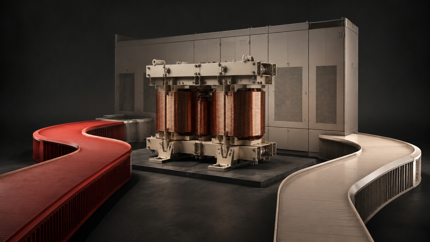
When evaluating a low-frequency UPS, ask where the transformer sits and which power paths remain isolated. The label alone does not establish isolation during bypass, motor-starting capability or compatibility with the site grounding design. A path drawing and mode-specific performance data are more useful than a general promise of robustness.
Translate the purchase term into an engineering requirement
Buyers may encounter “low-frequency UPS,” “industrial-frequency UPS” or “transformer-based UPS” in industrial catalogues. Use those terms to find candidates, then ask the supplier to identify the actual transformer arrangement. A product category is not a substitute for a single-line drawing, particularly when the plant specification calls for galvanic isolation or a defined neutral arrangement.
State the purpose of isolation: for example, the project engineer may require separation between a source and a protected distribution circuit. Naming that purpose makes the supplier’s answer testable. Do not infer galvanic isolation merely from the presence of a voltage-conversion component; ask for the winding arrangement and the connections relevant to the specified isolation boundary.
Trace the inverter, battery and bypass paths
Eaton’s comparison of transformer-based and transformer-free UPS designs illustrates why transformer location matters: isolation can be provided in different system arrangements. That is background engineering context, not evidence for a Highidea configuration. Ask the selected manufacturer to mark the path your load will actually use in each mode.
Use the following drawing review during technical clarification. Every answer should refer to the proposed configuration, including external accessories. “Transformer included” is incomplete if the bypass wiring can send power around it.
Operating condition | Trace on the drawing | Question to close |
|---|---|---|
Normal inverter supply | Source → conversion stages → load | Where is the required isolation boundary? |
Battery operation | Battery → inverter → load | Is the same boundary maintained? |
Static bypass | Bypass source → switch → load | Does this path pass through or around the transformer? |
Maintenance bypass | Service supply route → load | What protection remains during maintenance? |
Separate isolation from high-inrush capability
An industrial UPS may supply controls, contactors, actuators and other loads with very different starting behavior. The existence of a transformer does not specify how much current the inverter can deliver, for how long, or how far the output voltage may dip. Ask for overload curves by operating mode and compare them with the actual event sequence.
Consider a control cabinet that runs steadily at a modest load but energizes several contactors together after power returns. A useful inquiry describes that restart event, not only the running kW. Ask whether loads can be sequenced and what happens if the UPS transfers to bypass during the event. This is a design example, not a claim that any particular Highidea unit can start the equipment.
Include the installation in the comparison
Request dimensions, mass, access clearances and heat-loss data for the complete proposed system. If a transformer is external, include its enclosure, connections and service space in the layout. Compare efficiency at the expected operating load with equivalent accessories included, rather than comparing one bare UPS with another supplier’s complete installation.
Give the site engineer the neutral, protective-earth and bypass drawings for review. The appropriate arrangement depends on the distribution system and project rules. This article does not prescribe a field wiring method; installation, protection coordination and any energized tests must be handled by qualified personnel.
Where Highidea GD and GX33 enter the discussion
Highidea lists the GD 6–30K as an industrial-frequency online UPS with 110 V output, making it a candidate for specialty-voltage industrial inquiries. The GX33 is a separate three-phase industrial-frequency UPS family. Treat them as different starting points for technical selection, not as interchangeable products with a shared electrical specification.
Send the required voltage, phase arrangement, load event sequence and isolation purpose to Highidea. Ask for the exact proposed model, transformer placement, bypass drawing and load-performance evidence. A 110V UPS requirement does not establish the required input supply or the behavior of the bypass path, and a three-phase family name does not settle the project capacity.
A decision record procurement can use
Approve the architecture only when the drawing and the performance response describe the same configuration. Keep a list of accepted deviations so a lower-priced alternative does not silently remove an isolation component or change the maintenance arrangement. The objective is a system that meets the operating requirement, not the largest transformer or the broadest catalogue claim.
- Purpose and location of isolation, identified on the supplier drawing.
- Source-to-load path and available protection in every operating mode.
- Actual load sequence matched to output and overload behavior.
- Complete installation footprint, heat and access requirements.
- Named engineering approver and agreed configuration-specific acceptance evidence.
Sources and further reading
These references explain the technical context. Product selection and acceptance remain specific to the proposed equipment and installation.
Eaton: The high-power UPS: transformer-based and transformer-free designs
IEC: IEC 62040-3:2021 — UPS performance and test requirements
FAQ
Frequently asked questions
Does a low-frequency UPS always isolate the load in bypass?
Do not assume so. Verify the bypass and maintenance routes on the actual system drawing and identify whether they cross the required isolation boundary.
Is a transformer-based UPS automatically better for motors?
No blanket conclusion follows from the transformer label. Match starting demand, duration, voltage-dip tolerance and restart sequence to model-specific overload and transfer behavior.
Can an external transformer be considered?
It can be part of an engineered proposal. Include its location, winding arrangement, loss, installation requirements and effect on every power path in the comparison.
Related
Products, solutions & further reading.
Put this into practice
Need help specifying the right unit?
Share the load, voltage, runtime, environment and destination for a configuration review.