Coordinating UPS Output Protection in Battery and Bypass Modes
By Highidea Power · 23 October 2026 · 4 min read
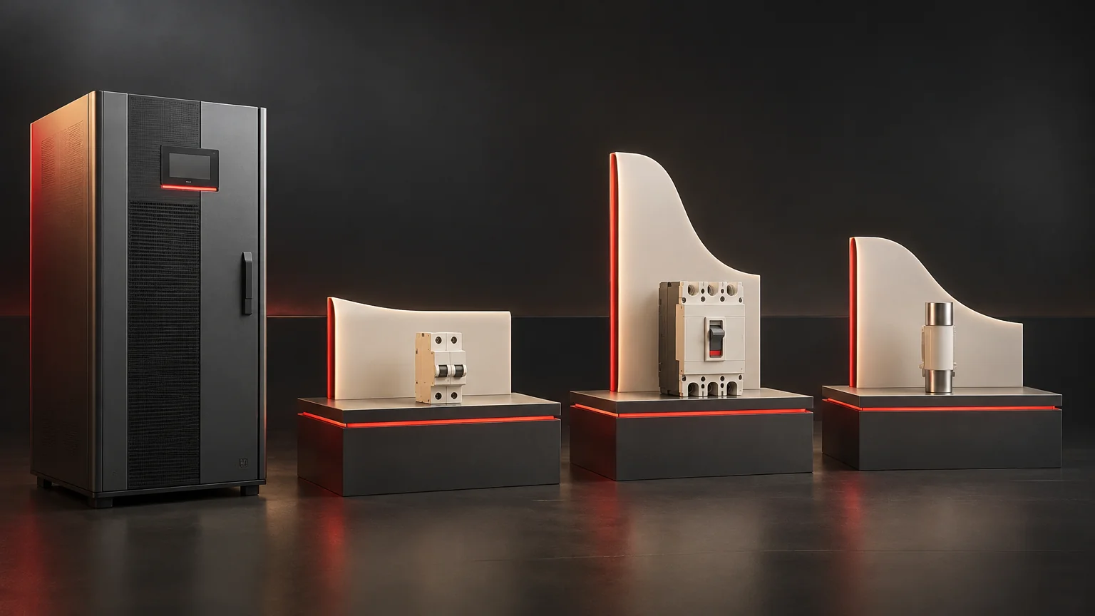
Downstream protection must be assessed against the source feeding a fault at that moment. UPS inverter operation and bypass operation can provide very different fault-current behavior, so normal load capacity alone cannot establish selective clearing. For a Highidea industrial UPS project, define the branches you need to preserve and request the selected configuration’s mode-specific information for the electrical designer’s coordination study.
Define what selective clearing should preserve
A branch fault should be considered together with its effect on other loads. Selectivity aims to disconnect the intended faulted section while retaining the appropriate healthy sections. The UPS protecting its own power electronics is a related but different objective.
Begin with the actual distribution drawing. Identify each branch, the protective devices and the loads affected if a common upstream device operates. State the required outcome for the fault scenarios the designer will evaluate. “Protection included” is too broad to specify whether one failed branch may interrupt every load on the UPS.
Also record the load’s tolerance to voltage disturbance. A protective device eventually clearing a fault does not establish that neighboring equipment can ride through the disturbance before clearance. The intended service outcome therefore belongs in the study alongside the electrical equipment data.
Compare sources by current and time
Eaton’s power-distribution white paper explains that transformers, generators and UPS inverters have distinct fault responses. An inverter can limit its contribution electronically, and that contribution may change over a defined duration. A branch protective device must be evaluated against the available current-time behavior, not against a presumed utility-like source.
Bypass provides another path whose behavior depends on the bypass source, upstream protection and circuit impedance. Transfer to that path is also conditional on the UPS design and circumstances. It cannot be assumed to solve every fault when bypass is unavailable or unsuitable.
Battery and normal inverter operation should be identified explicitly in the requested information. Ask the supplier which documented behaviors apply to each condition. Do not assign one common fault-current multiple merely because the same AC load runs successfully in both states.
Build a mode-by-mode input matrix
Study condition | Source information and paired distribution inputs |
|---|---|
Inverter supplying the load | Source: applicable fault-current limitation and duration. Pair with: branch device characteristics and fault-path impedance. |
Battery supplying the inverter | Source: relevant battery-mode limits and response. Pair with: the same fault location and intended clearing outcome. |
Bypass supplying the load | Source: fault level and bypass-path capability. Pair with: upstream and downstream device data. |
Transfer-dependent scenario | Source: conditions and availability for the intended transfer. Pair with: load disturbance tolerance and protection interaction. |
Transformer in the path | Source: actual position and relevant electrical characteristics. Pair with: fault location, grounding arrangement and conductors. |
Changed configuration | Source: updated ratings and behavior. Pair with: revised branch loads and protective devices. |
The matrix organizes inputs; it does not set protective-device ratings or authorize a fault test.
Put the transformer in the actual path
A transformer-based UPS label does not define every fault loop. Its physical position relative to inverter, bypass and distribution matters. The designer needs the actual single-line arrangement and relevant transformer information to assess the chosen fault scenarios.
This is why a normal kVA rating cannot close the protection question. It describes an operating capacity, while fault clearing involves available current over time and device behavior. Keep these data sets separate in the procurement request, then bring them together in the system study.
Use the isolation-through-every-path guide to understand a separate transformer-related question. Isolation claims and protection selectivity should each have their own supporting review.
Resolve a mismatch before equipment selection is final
Consider a hypothetical branch device selected using only the upstream utility fault level. If the intended battery-mode inverter contribution is insufficient to produce the assumed operation, the study’s basis has changed. The designer must reassess the arrangement using the correct source information; simply choosing a larger UPS from a normal-load table is not a demonstrated remedy.
Likewise, changing a branch device or adding a transformer may alter coordination elsewhere. Keep a revision record so equipment substitutions return to the responsible designer. The bypass guide helps identify the paths whose availability must be stated clearly.
Prepare the Highidea project information
Highidea offers industrial-frequency GD and GX33 ranges as well as three-phase online 33ET configurations. Share the single-line drawing, critical branches, load requirements and intended modes with Highidea. Request the information applicable to the selected configuration and identify who will complete the project protection study.
Actual device selection, settings and installation remain work for the responsible qualified electrical team using current product documentation. Do not create a live short circuit or disable protection to demonstrate this planning matrix.
Primary reference
- Eaton: Different power source behavior and effect on the power distribution, source behavior and coordination principles.
FAQ
Frequently asked questions
Does sufficient UPS kVA prove a branch breaker will clear selectively?
No. Normal capacity and fault-clearing behavior require different information and evaluation.
Can bypass always provide the required fault current?
No. Its source, availability, path capability and transfer conditions must be established for the scenario.
Must coordination be revisited when only one branch changes?
Review the change with the designer. A local substitution can affect the common source or protection shared with other branches.
Related
Products, solutions & further reading.
Put this into practice
Need help specifying the right unit?
Share the load, voltage, runtime, environment and destination for a configuration review.